 Professional Flip-Chip Packaging Substrate Supplier

Microwave Circuit PCB Manufacturer. specializes in producing high-frequency printed circuit boards designed for microwave and RF applications. These manufacturers use advanced materials and precision fabrication techniques to create PCBs that handle signals in the microwave range, ensuring excellent performance and signal integrity. Their expertise includes designing and producing boards for applications such as communication systems, radar, and satellite technology, where high-frequency performance and reliability are crucial. By leveraging cutting-edge technology and strict quality control, these manufacturers provide essential components for modern high-frequency electronics.
Microwave circuit printed circuit boards (PCBs) are specialized PCBs designed to operate at microwave frequencies, typically ranging from 300 MHz to 300 GHz. These PCBs are crucial for a wide range of applications, including telecommunications, radar systems, satellite communications, and medical devices. This article explores the concept, structure, materials, manufacturing process, applications, and advantages of microwave circuit PCBs.
What is a Microwave Circuit PCB?
A microwave circuit PCB is a type of printed circuit board specifically engineered to handle microwave frequency signals. These PCBs are designed to minimize signal loss, maintain signal integrity, and ensure reliable performance in high-frequency applications. Microwave circuit PCBs are characterized by their ability to operate efficiently at frequencies where standard PCBs would suffer from excessive signal degradation and loss.
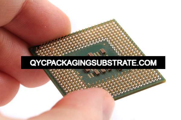
Microwave Circuit PCB Manufacturer
Microwave circuit PCBs are used in applications where high-frequency signal transmission is critical. These applications demand PCBs with specialized materials, precise design, and meticulous manufacturing processes to ensure optimal performance.
Structure of Microwave Circuit PCBs
The structure of microwave circuit PCBs is meticulously designed to handle high-frequency signals while minimizing signal loss and interference. Key structural elements include:
The substrate material is one of the most critical components in microwave circuit PCBs. Commonly used materials include PTFE (Polytetrafluoroethylene), Rogers laminates, and ceramic-filled substrates. These materials offer low dielectric loss, stable dielectric constant, and excellent thermal properties.
The conductive layers are typically made of copper, which provides excellent electrical conductivity. The copper layers are carefully patterned to create the required transmission lines, ground planes, and other circuit elements.
Dielectric materials are used to insulate the conductive layers and ensure minimal signal loss and interference. The choice of dielectric material is crucial, as it affects the PCB’s electrical performance at high frequencies.
Microwave circuit PCBs often use microstrip and stripline structures to route high-frequency signals. These structures are designed to maintain controlled impedance and minimize signal degradation.
Vias, including through-hole vias, blind vias, and microvias, are used to create vertical electrical connections between different layers of the PCB. These structures must be designed to minimize inductance and capacitance, which can affect high-frequency performance.
The surface finish is applied to protect the copper traces and ensure reliable soldering. Common finishes include ENIG (Electroless Nickel Immersion Gold) and immersion silver, which provide good conductivity and corrosion resistance.
A protective layer of solder mask is applied to the PCB to prevent solder bridges and protect the circuitry from environmental damage.
Materials Used in Microwave Circuit PCBs
The choice of materials in microwave circuit PCBs is crucial for their performance and reliability. Common materials include:
PTFE, Rogers laminates, and ceramic-filled substrates are widely used for their low dielectric loss, stable dielectric constant, and excellent thermal properties. These materials ensure minimal signal loss and high performance at microwave frequencies.
Copper is the primary conductive material used in microwave circuit PCBs due to its high electrical conductivity and thermal performance. In some cases, other metals like gold or silver may be used for specific applications requiring higher conductivity or corrosion resistance.
Advanced dielectric materials such as epoxy resin, polyimide, and PTFE are used to insulate the conductive layers. These materials offer excellent electrical insulation, thermal stability, and chemical resistance.
ENIG, immersion silver, and immersion tin are common surface finishes that improve solderability and protect the PCB from oxidation and corrosion.
Epoxy-based solder masks are commonly used to protect the circuitry and prevent solder bridges during the assembly process.
The Manufacturing Process of Microwave Circuit PCBs
The manufacturing process of microwave circuit PCBs involves several precise and controlled steps to ensure high quality and performance. Key steps include:
The design phase involves creating detailed schematics and layouts using computer-aided design (CAD) software. The layout includes the arrangement of conductive traces, microstrip and stripline structures, vias, and other features necessary for the microwave circuit’s functionality.
High-quality raw materials, including substrate materials, copper foils, and dielectric materials, are prepared and inspected to ensure they meet the required specifications.
The substrate material and copper foils are laminated together using heat and pressure to form a unified multilayer structure. This step involves precise alignment and control to ensure the layers are properly bonded.
Vias and microvias are drilled into the PCB to create vertical electrical interconnections. These holes are then plated with copper to establish conductive pathways.
The circuit patterns are created using photolithographic processes. This involves applying a photosensitive film (photoresist) to the copper surface, exposing it to ultraviolet (UV) light through a mask, and developing the exposed areas to reveal the desired circuit patterns. The PCB is then etched to remove the unwanted copper, leaving behind the circuit traces.
Dielectric layers are applied to insulate the conductive layers. This step involves coating the PCB with a dielectric material and curing it to form a solid layer.
Surface finishes such as ENIG, immersion silver, or immersion tin are applied to the contact pads to improve solderability and protect against oxidation. These finishes are applied using plating or immersion techniques.
A protective layer of solder mask is applied to the PCB to prevent solder bridges and protect the circuitry from environmental damage. The solder mask is typically applied using screen printing or photolithographic techniques.
The final PCBs undergo rigorous inspection and testing to ensure they meet all performance and reliability standards. Electrical testing, visual inspection, and automated optical inspection (AOI) are used to identify any defects or irregularities.
Application Areas of Microwave Circuit PCBs
Microwave circuit PCBs are used in a wide range of electronic applications across various industries. Key application areas include:
Microwave circuit PCBs are essential in telecommunications equipment, including base stations, antennas, and signal processing units. Their high performance and reliability support high-speed data transmission and communication.
In radar systems, microwave circuit PCBs are used to transmit and receive high-frequency signals. These PCBs ensure accurate signal processing and reliable operation in defense, aviation, and weather monitoring applications.
Microwave circuit PCBs are used in satellite communication systems, including transponders, receivers, and transmitters. They provide the necessary performance and reliability for long-distance communication and data transmission.
Microwave circuit PCBs are used in medical devices such as diagnostic equipment, imaging systems, and patient monitoring systems. Their precision and reliability support advanced medical technologies and accurate diagnostics.
In consumer electronics, microwave circuit PCBs are used in devices such as smartphones, tablets, and wireless communication systems. Their high performance and compact size support the miniaturization and functionality of modern consumer electronics.
Advantages of Microwave Circuit PCBs
Microwave circuit PCBs offer several advantages that make them indispensable for modern electronic applications. These advantages include:
Microwave circuit PCBs are designed to operate efficiently at high frequencies, ensuring minimal signal loss, low distortion, and reliable performance.
The precise design and advanced materials used in microwave circuit PCBs ensure accurate signal transmission and processing, making them ideal for applications requiring high precision and reliability.
The rigorous manufacturing process and high-quality materials ensure that microwave circuit PCBs meet stringent performance and reliability standards, reducing the risk of failures in real-world applications.
Microwave circuit PCBs can be used in various applications, from telecommunications to radar systems and medical devices, making them versatile and adaptable to different industry needs.
The use of standardized manufacturing processes and materials in microwave circuit PCBs allows for cost-effective production, making them an economical choice for high-volume electronic applications.
FAQ
What materials are commonly used in the substrate of microwave circuit PCBs?
Common materials used in the substrate of microwave circuit PCBs include PTFE, Rogers laminates, and ceramic-filled substrates. These materials provide the necessary low dielectric loss, stable dielectric constant, and excellent thermal properties required for high-frequency applications.
How do microwave circuit PCBs improve the performance of telecommunications equipment?
Microwave circuit PCBs improve the performance of telecommunications equipment by enabling efficient high-frequency signal transmission, ensuring minimal signal loss and interference, and providing reliable performance in demanding environments.
Can microwave circuit PCBs be used in radar systems?
Yes, microwave circuit PCBs are highly suitable for radar systems. They are used to transmit and receive high-frequency signals, ensuring accurate signal processing and reliable operation in defense, aviation, and weather monitoring applications.
What are the key advantages of using microwave circuit PCBs in satellite communications?
The key advantages of using microwave circuit PCBs in satellite communications include high-frequency performance, precision and accuracy, enhanced reliability, versatility, and cost efficiency. These benefits support long-distance communication and data transmission in satellite systems.